Multidisciplinary Treatment of an Ankylosed Tooth in the Anterior Region
Машинний переклад
Оригінальна стаття написана мовою ES (посилання для прочитання) .
The ankylosis of a tooth results from trauma during the growth period, fusing the cementum or dentin to the alveolar bone. The tooth or teeth do not erupt, and their position remains out of the occlusal plane.
The solution to an ankylosed tooth in the anterior front is difficult.
There are prosthodontic and/or surgical solutions, with or without orthodontics, such as luxation of a tooth or extraction followed by implant with graft. These procedures leave a step in the occlusal plane and a gingival margin that is difficult to resolve.
The best results are obtained when orthodontics is combined with surgery to displace the dentoalveolar fragment as a block and subsequent management with orthodontic methods and/or osteogenic distraction.
We present a case in which osteotomies of the dentoalveolar fragment of an incisor in the process of root resorption were performed, followed by orthodontic management with brackets using the tooth. Once the tooth was leveled and the occlusal plane adjusted, it was complexly replaced with grafts and implants.
Anamnesis:
- Name: B.LL.
- Age: 18 years.
- Medical history: Previous trauma with avulsion of the permanent upper left central incisor and subsequent reimplantation of the same. No history of systemic diseases, current pharmacological treatment, or allergies.
- Reason for consultation: Lack of aesthetics in the anterior front.
Diagnosis:
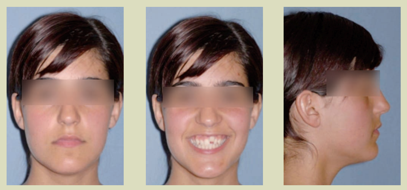
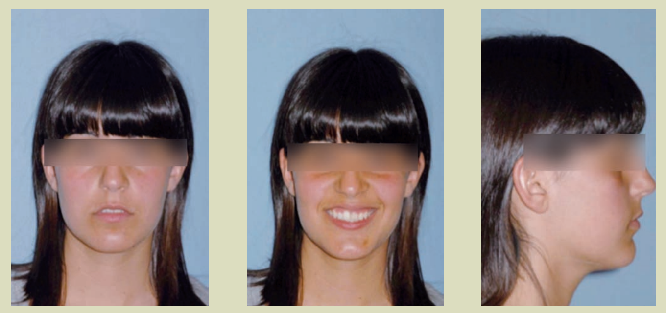
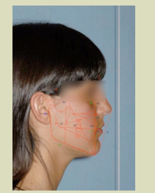
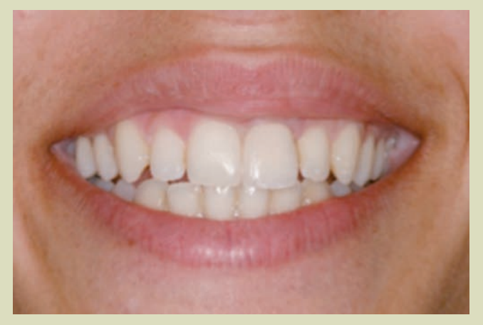
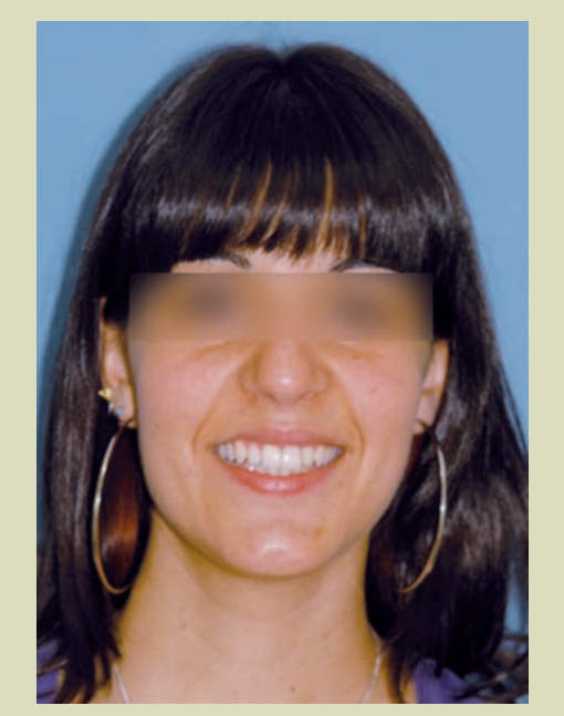
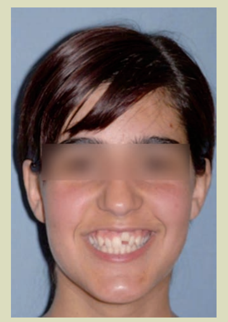
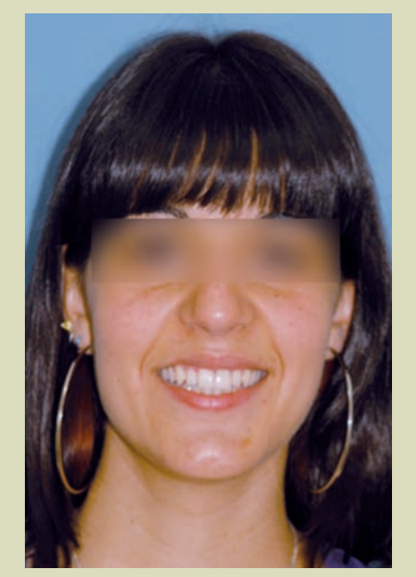
1. Facial analysis (Figs. 1a, 1b, and 1c)
- Gummy smile.
- Smile aesthetics altered by the apical position of 21.
- Straight profile.
- Slight deviation of the upper midline to the left.
2. Radiographic analysis
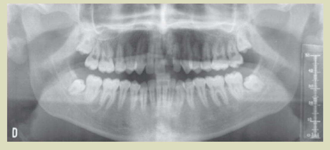
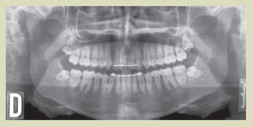
2.1. Panoramic radiography. (Fig. 5)
- Permanent dentition.
- 21 with internal root resorption, external resorption, and ankylosis.
- Presence of developing third molars.
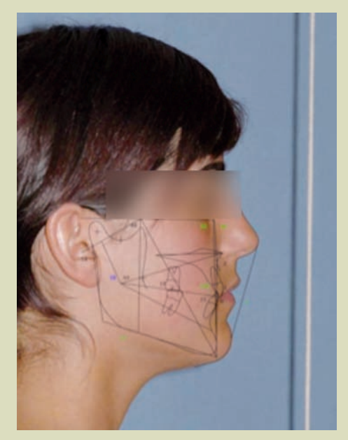
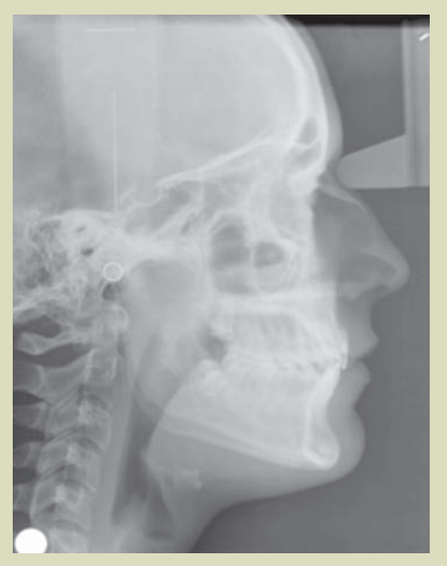
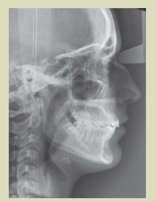
2.2. Lateral cephalometric radiography of the skull and cephalometric tracing. (Fig. 3 and 4)
- Mesofacial.
- Class I skeletal.
- Incisors correctly positioned relative to their bony bases.
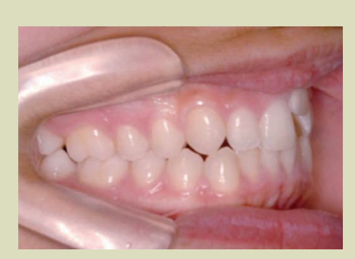
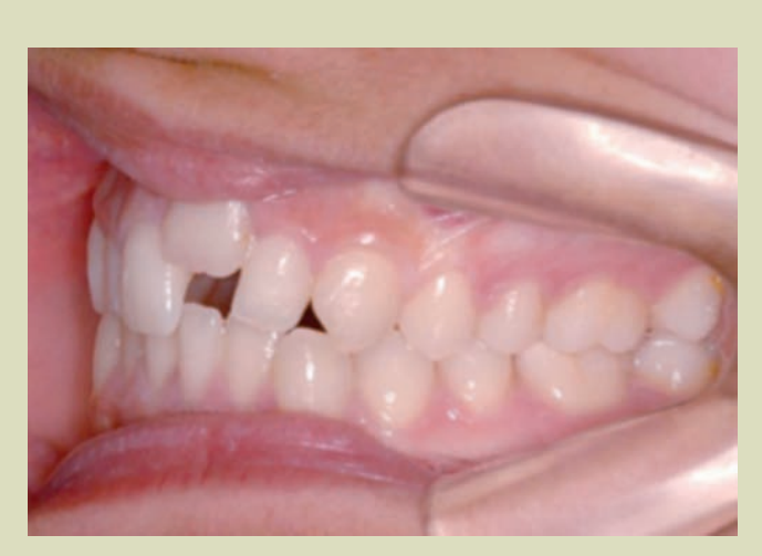
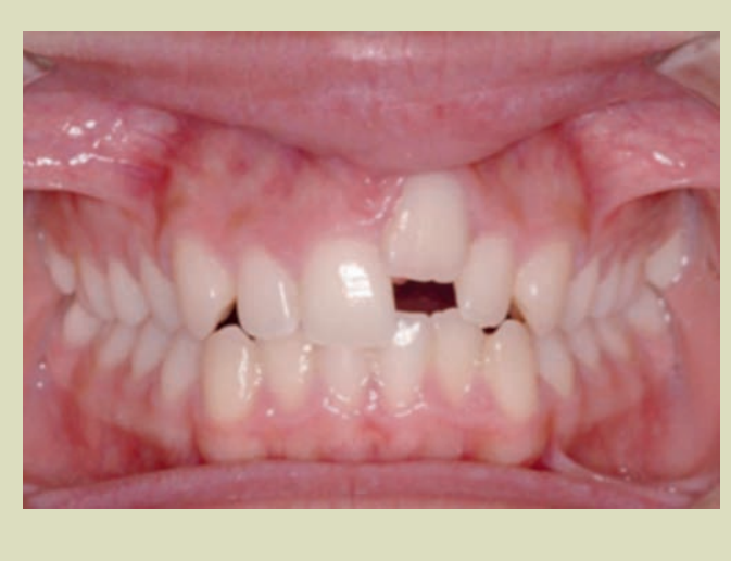
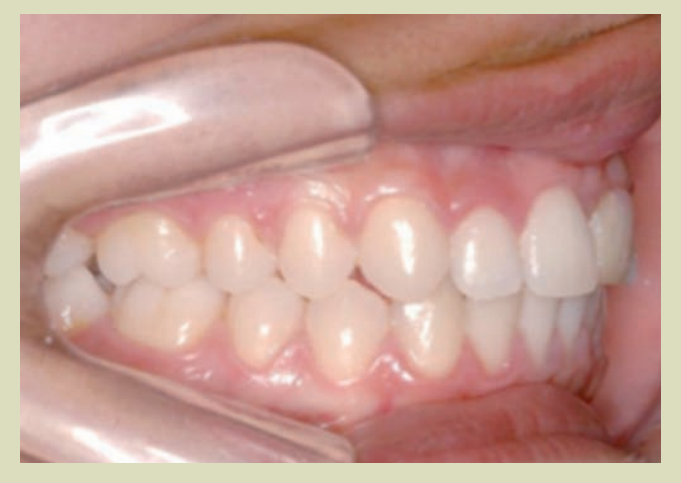
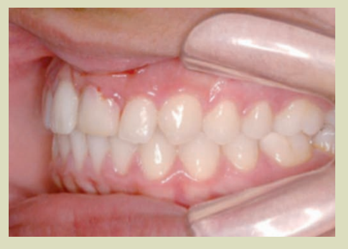
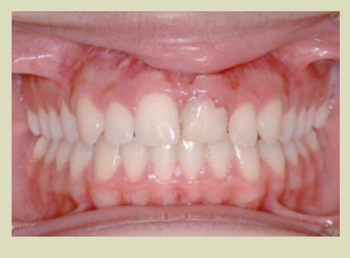
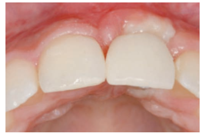
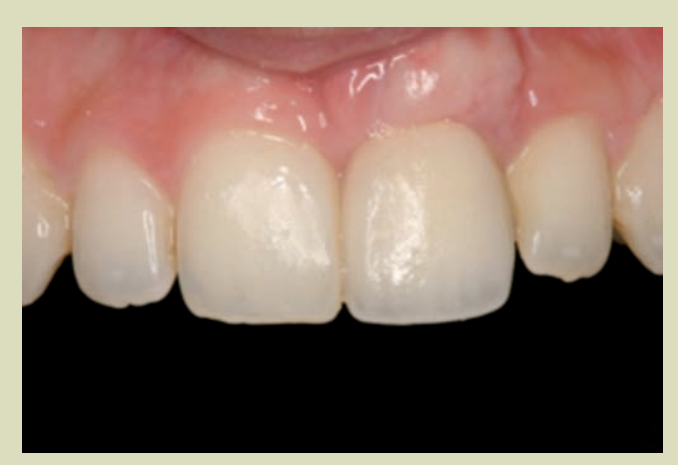
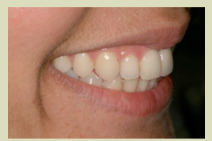
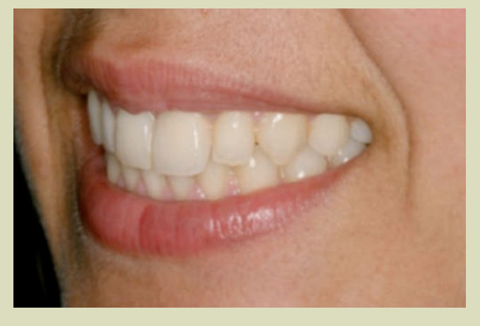
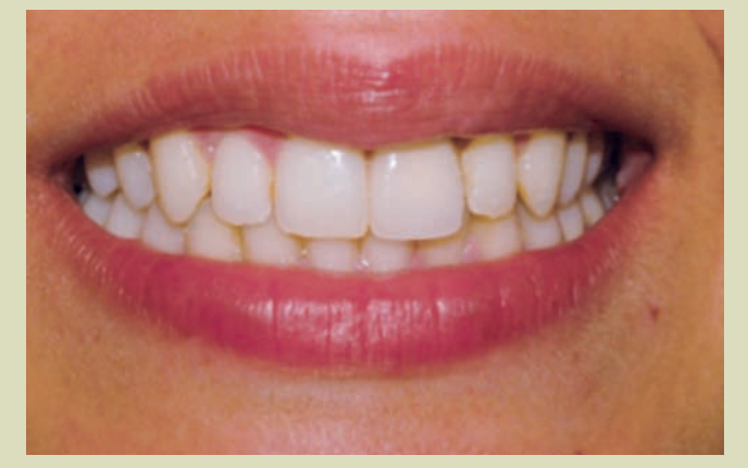
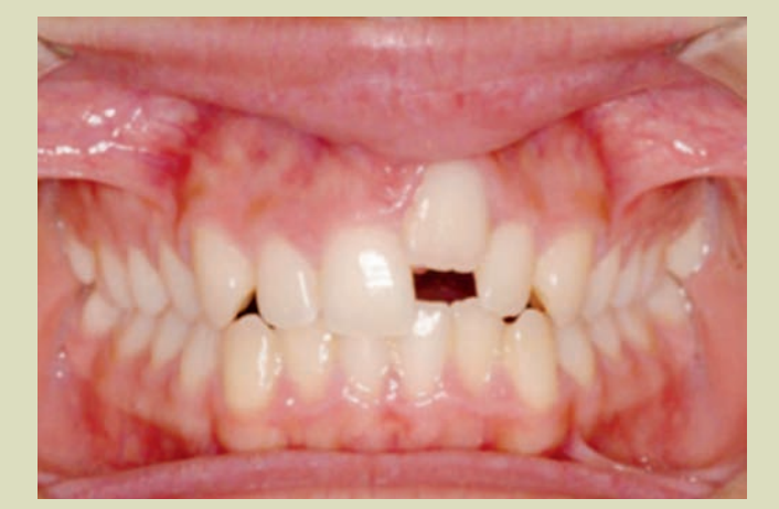
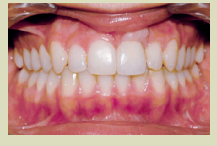
3. Intraoral analysis (Figs. 2a, 2b, and 2c)
- Gingival margin of tooth 21 very uneven due to ankylosis.
- Deviation of the upper midline 2 mm to the left.
- Class I molar and slight Class II right canine.
- Class I molar and left canine.
- Overjet: 2 mm.
- Overbite: 2.5 mm.
- D.O.D.: Upper: - 2 mm. Lower: - 1.3 mm.
Treatment
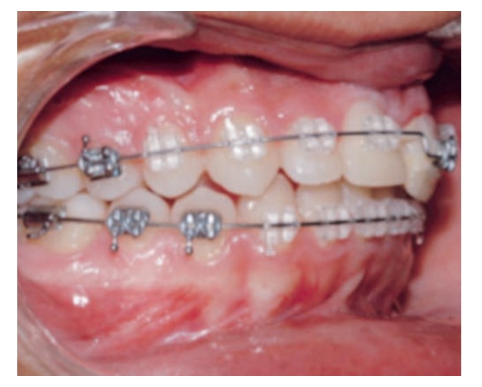
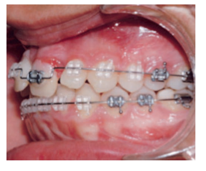
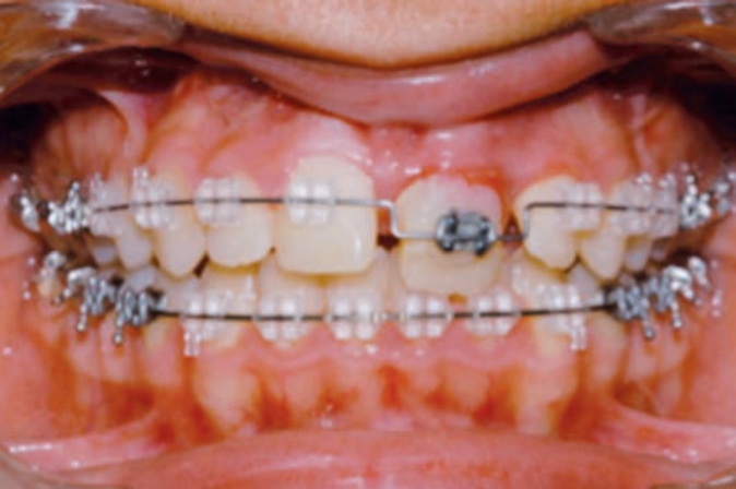
Pre-surgical orthodontics (Figs. 6 and 7)
The bonding of brackets was carried out considering that an adequate root divergence was desired in the teeth adjacent to the ankylosed central incisor, which is why the position of the bracket of the upper right central incisor was initially varied so that it expressed the tip to a greater extent than that incorporated in the bracket prescription (5º) and it was not necessary in the case of the canine, as it already has a sufficient amount of tip to move the root distally (13º).
During the course of the pre-surgical orthodontic treatment, space was opened for the 21, overcorrecting it in order to generate a sufficient amount to facilitate the subsequent surgery and descent of the fragment. This meant that the upper midline was deviated to the right in relation to the lower midline at this phase of the treatment.
A conventional sequence of arches was followed until sufficient root divergence and space between the crowns was obtained (0.14, 0.18, 19x25 of NiTi Thermal, 0.20 of Steel).
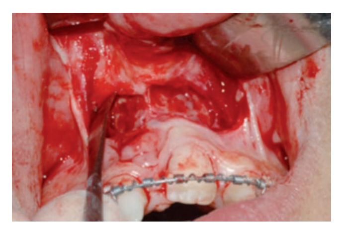
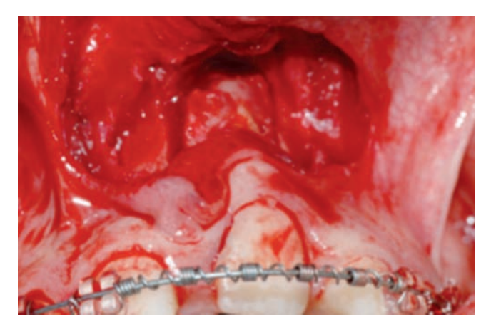
Surgery
Under general anesthesia, a horizontal incision of 8 mm was made above the gingival margin of the ankylosed tooth. A mucoperiosteal flap was raised that extends one tooth on each side of the fragment to be cut.
The upper cut of the block is made 4-5 mm above the apex and through tunnels, vertical cuts to the alveolar crest. The procedure was performed with a BTI ultrasonic scalpel with a very fine tip. At all times, the palatine mucosa and the bridge of keratinized gum around the tooth to be osteotomized were preserved.
The block had a trapezoidal design to slide the bone segment. Once the palatine cortex was fractured, the fragment was mobilized freely. The placement of a distractor was discarded due to the difficulty of its location, the challenging management of the vector, the need for a second surgery, and the cost.
Post-surgical Orthodontics (Figs. 8a, 8b, and 8c)
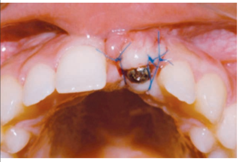
Once the surgery was performed, an 8-day latency period was waited, and traction began by cementing a bracket on the crown of 21 as gingival as possible and tying it distally to the steel arch. Subsequently, the extrusion of the fragment continued using a double arch technique (base arch of 19x25 Steel and superimposed also passing through 21, of 0.14 Thermal NiTi).
At the moment the alignment of the slot of bracket 21 was achieved with that of the other brackets, its extrusion was continued by overcorrecting its position until the alveolar process matched that of the adjacent teeth (the level desired by the implantologist and the prosthodontist). The time used for the descent of the fragment was 2 months.
Ultimately, space closure and arch coordination were performed. During almost the entire phase of post-surgical orthodontics, light intermaxillary elastics were used with the initial goal of minimizing the side effects of traction and subsequently achieving a correct settling and intercuspation of the opposing teeth. The orthodontic treatment lasted for 16 months.
Final (Figs. 9-13)
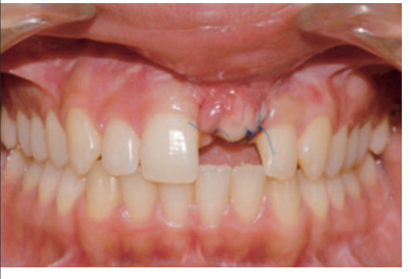
Subsequently, once the orthodontics was completed and considering that the tooth had a poor prognosis, it was extracted. A period of two months was allowed to avoid losing more keratinized gum, and a monocortical bone graft taken from the ascending ramus of the mandible was placed, taking advantage of the extraction of the lower third molar. The graft was secured with a Martin screw 1.6x11 mm and a resorbable collagen membrane was placed.
After four months, the state of the bone graft was evaluated, and once its stability and minimal resorption were confirmed, a BTI implant of 4x13 with internal connection and a subepithelial connective tissue graft were placed, which was secured with nylon 5/0. The postoperative course was without complications.
After four months, the second phase of the implant and a new subepithelial connective tissue graft was performed using tunneling.
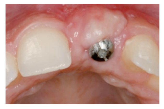
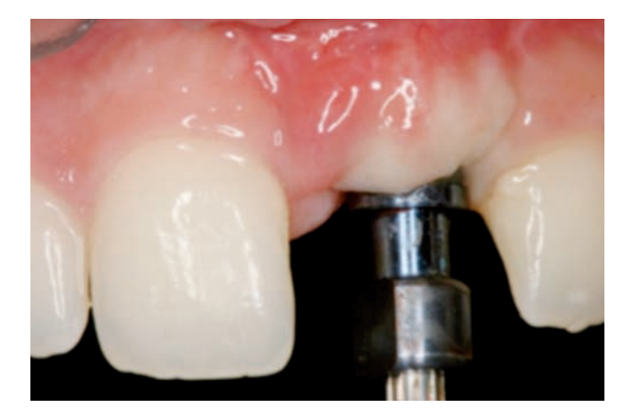
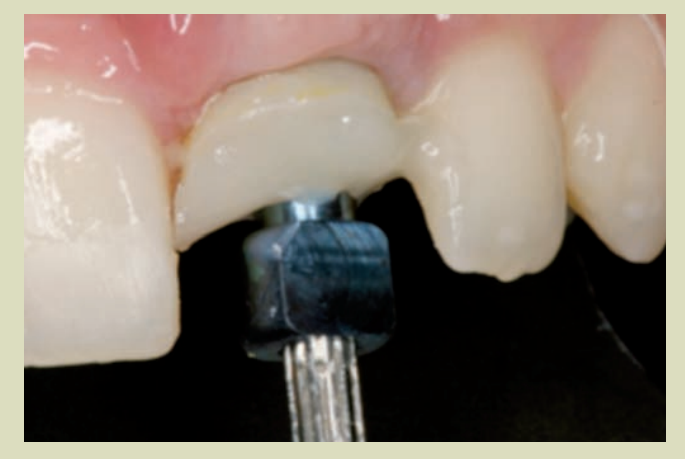
Implant (Figs. 14 and 15)
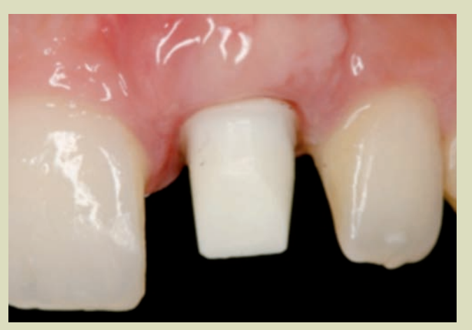
Restorative treatment (Figs. 16-18)

After the tissue healing phase and implant osteointegration, we proceed to restore the missing tooth. The patient presents a flat gingival contour and overcontoured at the vestibulolingual level, the mesiodistal space of the 21 is 10 mm and the width of the 11 is 9 mm, so we need to compensate for the discrepancy by adding 0.5 mm mesially to the 11.
Provisionalization phase and soft tissue modeling (Figs. 19-24)
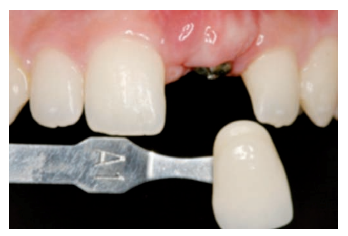
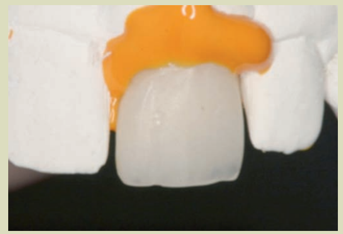
The first impression of the implant is taken using an open tray technique and addition silicone, for the fabrication of a screw-retained acrylic resin provisional crown. The base color A1 and existing characterizations are selected.
The provisional is placed in the mouth, modifying the cervical contour by applying slight pressure on the gingival tissue. A direct composite restoration is performed on the mesial of tooth 11 to distribute spaces and achieve symmetry between both incisors.
The patient attends the consultation in a week, 15 days, and a month to modify the provisional until achieving the desired gingival contour. (Figs. 25 and 26)
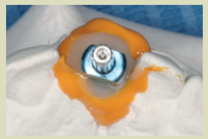
The individualized transfer is placed in the mouth and a new impression is taken with an open tray. (Fig. 27)
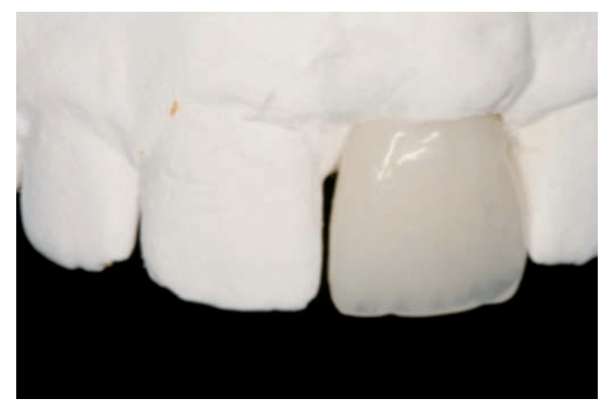
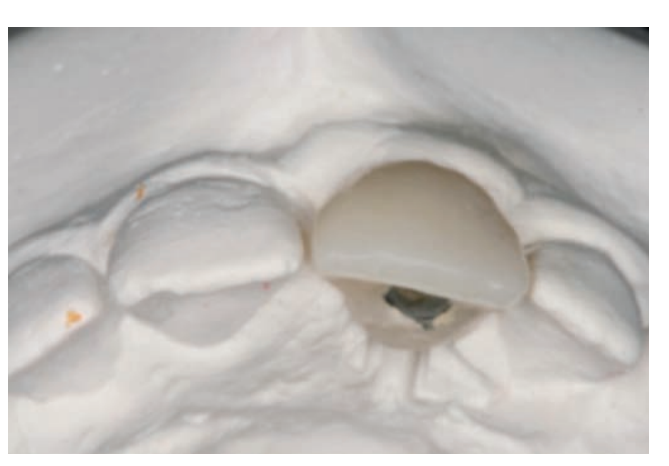
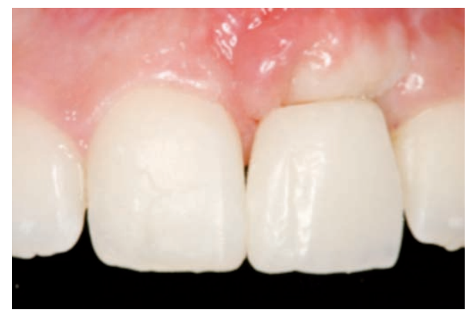
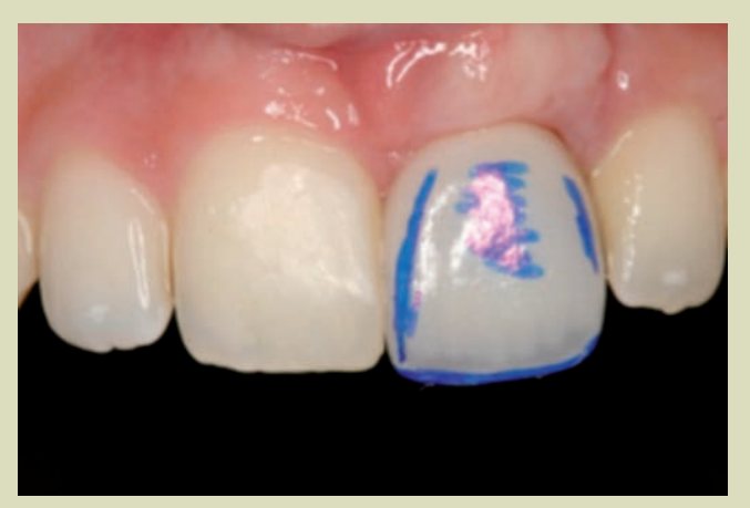
The final restoration will be a zirconia crown cemented onto an individualized zirconia abutment. The necessary tests and modifications are performed, and the final restoration is placed. (Figs. 28-33)
Retention (Figs. 34-36)
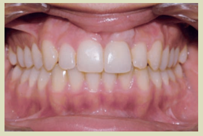
Comparison start/end (Figs. 37-40)
Discussion
The combination of orthodontic and surgical treatments allows, in a predictable and safe manner, to achieve an optimal result in the management of ankylosed teeth in infraocclusion and especially with different gingival heights. The decision to use or not use distractors will depend on the surgeon.
The use of distraction devices has drawbacks; the surgery requires a greater approach with difficulties in such small fragments to place the distractor, with potential problems with the osteosynthesis screws, difficulties in correcting the vector, hygiene issues, and discomfort.
A second surgery is also necessary to remove the distractor.
In our case, we have used the concept of floating bone to control the displacement and position of the dentoalveolar fragment, in which the osteotomized fragment has been controlled using intermaxillary elastics before its consolidation. The use of orthodontic appliances allows for a finer and more predictable adjustment.
The ankylosed tooth was mobilized even below the occlusal plane in 8 weeks. Sometimes, intrusion of adjacent teeth may occur, requiring intermaxillary elastics.
Once it has reached the appropriate position, although in this case we overcorrected, it is stabilized with a flat arch, and four months after the surgery, there is neoformed bone.
Root resorption is common before or after the treatment of ankylosed teeth. In our case with clear signs of resorption prior to treatment, the tooth was used to facilitate the transport of the dentoalveolar fragment following the concept of floating bone to carry it even below the occlusal plane, improving the height of the alveolar bone and the gingival margin of the treated tooth without signs of recession and good harmony with the adjacent teeth. This is fundamental and will allow us to plan an implant in the anterior sector, which is always difficult.
Fé Serrano Madrigal, César Colmenero Ruiz, Javier Prieto Serrano, Lucía Esteban-Infantes Corral